Ranchview High School · NASA HUNCH SFT 2026–27 · LLASO Project 2

Project

LIFT

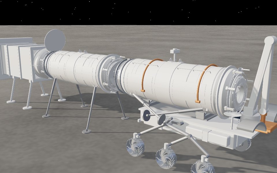
An autonomous lunar rover that picks up a landed cargo module, carries it across open regolith from the landing pad, and docks it to the habitat through a dust-sealed port. Nobody has to suit up and go outside.

Project L.I.F.T. mission patch: a six-wheeled rover lifting a cargo module with its arm on the lunar surface, Earth and the habitat behind it

The problem · LLASO-P2-XPORT-2026

A 40-foot cargo module lands on the Moon, kilometers from the habitat so its rocket plume can't sandblast the base. Someone has to bring it home and plug it into a pressurized port. On the Moon, that someone should be a robot.

Route
2km

Storyboard separation between the landing pad and the habitat.

Gravity
1/6g

Lighter loads, but less traction and an easier tip-over with a raised module.

Spacewalks
0EVA

Nominal transport can't require an astronaut to go outside.

Dock opening
1–2m

Needs a dust-sealed port, closed off before the module hatch opens.

Requested byNASA HUNCH / Kennedy Space Center, with NASA Robotics and Marshall Habitation.
DeliverableA concept prototype robot, or high-fidelity CAD and simulation with a demonstrated navigation and docking sequence.
Cargo4 ft × 2 ft Astrobotic pods, 20 ft containers and ~40 ft modules. Cylinders or rectangular prisms.
Loading mission model…

The mission · v11 route · current CAD rover · 84 s

Scroll to play a time-lapse.

M001 / 12

Touchdown

A cargo module lands on the pad, well outside the habitat's plume blast zone.

The rover · current CAD design

Built for 1/6 g

    L.I.F.T. · CAD assembly · carrying CM-02
    Drag to orbit · scroll-pinch to zoom
    Dust covers closed · clamps open

    The dock · dust-sealed port

    Seal first. Then open.

    1. 01
      Line upThe rover squares the module up with the port opening.
      —
    2. 02
      Dust covers openCovers stay shut until the module is inches away, so the seal faces never see open dust.
      —
    3. 03
      Into the portThe module’s docking ring goes into the port, and the orange guide ring centres it inside the IDSS contact limits.
      —
    4. 04
      Eight clamps closeClamps at 45° spacing pull the rings together for hard capture.
      —
    5. 05
      Brush seal verifiedA regolith brush boot compresses around the joint and the seal indicator turns green.
      —
    6. 06
      Hatch opensOnly now does the module hatch open to the pressurized habitat.
      —
    Initial contactIDSS limitApproach
    Closing speed0.05–0.10 m/s0.10 m/s
    Lateral offset≤ 0.10 m0.09 m
    Lateral rate≤ 0.04 m/s0.03 m/s
    Angular misalignment≤ 4°3.6°
    Limits from the IDSS Interface Definition Document, as modelled in the Lunar Surface Ops simulation. Approach values are illustrative.

    NASA Docking System (NDS) · built to the International Docking System Standard (IDSS)

    Soft catch. Hard lock.

    1. 01
      ExtendThe active NDS pushes its soft-capture ring out on six actuators. The passive side stays retracted.
      —
    2. 02
      ContactThree guide petals on each ring slide past each other and line the two rings up.
      —
    3. 03
      Soft captureA capture latch on each petal catches the other ring.
      —
    4. 04
      AbsorbThe six actuators give way under load and damp out the leftover motion.
      —
    5. 05
      Align and retractThe actuators line the two vehicles up and pull the ring back in.
      —
    6. 06
      Hard captureTwelve pairs of hooks close and seal the joint. The 0.8 m hatchway can open.
      —
    SystemNASA Docking System (NDS), NASA’s version of the IDSS
    StandardInternational Docking System Standard (IDSS), agreed in 2010 by NASA, Roscosmos, ESA, JAXA and the Canadian Space Agency
    Hatchway0.8 m (31 in) across
    Capture3 petals, 3 latches and 6 actuators, then 12 pairs of hooks
    Used onBoeing Starliner, the ISS docking adapters, Orion from Artemis III, and the nose of the L.I.F.T. cargo module
    Sources: International Docking System Standard · NASA, NDS Block 1 soft capture system
    Ring extended
    Loading CAD assembly…

    Watch it dock · CAD assembly animation · 52 s

    Scroll to play a time-lapse.

    Step 101 / 09

    Drive in

    L.I.F.T. carries module CM-02 toward the port, where module CM-01 is already docked.

    The challenge · 12 missions

    Mobility to invention

    The evolution · 12 builds

    From block-out to CAD

    Swipe for every build

    Lunar Surface Ops · interactive simulation

    Take the controls
    Lunar
    Surface Ops

    Runs in your browser · WASD to drive after takeover
    Priority dispatchLife-support spares and emergency parts move first. Ties go to the nearest pad.
    Route planningPaths bend around craters from 1 m to 2 km across and around boulder fields.
    Real docking limitsNDS and IDA port geometry, graded live against IDSS contact limits.
    Keyboard takeoverTake over from the autonomy at any time and drive the rover yourself with the keyboard.

    CDR prototype electronics · not yet built

    Electronics

    BNO085 IMUtilt and headingLimit switchesclaw and saddle clamps closedDock radiosecond RP2040-LoRa · port statusModule radio · optionalthird RP2040-LoRa · power bankPi Camera Module 3on the arm · reads the markersELP stereo camera · optionalin the nose · depth of the groundRPLIDAR C1 lidar360° obstacle scan on the mastRP2040-LoRa radio, 915 MHzon the rover · antenna on the mastRaspberry Pi Pico 2makes the six motor speed signalscounts the wheel encodersruns the servo board, IMUand switchesreads the battery voltagedrives the boom actuatortakes orders from the PiRaspberry Pi 5camera and printed markersstereo depth of the groundlidar obstacle scanroute followingmission steps: find, grip,carry, dockLoRa messages in and outinside the sealed body5 V 5 A converterpowers the Pi 5 · always on6 × 12 V gear motorswith encoders, one per wheelN20 size, 210:13 × TB6612 motor driverstwo motors eachPCA9685 servo driver16 channels2 × 35 kg servosboom · forearm3 × MG996R servosturret · wrist · claw3 × MG90S servostwo saddle clamps · balance rackLinear actuator · optionalpushes the boom for a 2 kg moduleDRV8871 driver · position feedbackMotor power11.1 V via the kill switch6 V converterservo powerKill switchcuts motor and servo powerthe Pi stays on3S LiPo, 2200 mAh11.1 V · on the balance rackwith a low-voltage alarm3S BMS · optionalbalance · protectiontaped to the batteryFusemain lineSolar panel · optional10 W, 12 V, semi-flexibleon top of the bodySolar charge boardoptional · CN3722set to 12.6 VI²CGPIOCSIUSBUSBUSBRADIO LINKUSBENCODERSPWM · DIRI²CDRIVEPWM × 8MOTOR AND SERVO SUPPLY5 V12 VDATAPOWEROFF THE ROVEROPTIONAL · COUNTED IN THE BUDGETALL GROUNDS TIED TOGETHER

    Sense

    Pi Camera Module 3On the arm. Reads the printed markers on the module and the dock.CSI → Pi 5
    ELP stereo camera (optional)In the nose. Two lenses in sync give the depth of the ground ahead.USB → Pi 5
    RPLIDAR C1 lidar360° obstacle scan on the mastUSB → Pi 5
    RP2040-LoRa radio, 915 MHzOn the rover, antenna on the mast. Talks to a second one in the dock and an optional third in the cargo module.USB → Pi 5
    BNO085 IMUTilt and headingI²C → Pico 2
    Limit switchesClaw and saddle clamps closedGPIO → Pico 2

    ↓

    Think

    Raspberry Pi 5Camera and markers, stereo depth, lidar, route following, the mission steps (find, grip, carry, dock) and LoRa messages. Inside the sealed body.
    Raspberry Pi Pico 2Motor speed signals, wheel encoders, the servo board, IMU, switches, battery voltage and the boom actuator.USB ↔ Pi 5

    ↓

    Act

    6 × 12 V gear motorsWith encoders, one per wheelSpeed pulses back to the Pico
    3 × TB6612 motor driversTwo motors eachPWM · direction from the Pico
    PCA9685 servo driver16 channelsI²C from the Pico
    2 × 35 kg servosBoom and forearmPWM from the PCA9685
    3 × MG996R servosTurret, wrist and claw
    3 × MG90S servosTwo saddle clamps and the balance rack
    Linear actuator (optional)Pushes the boom for a 2 kg module. Own DRV8871 driver, position feedback.PWM from the Pico

    ↓

    Power

    Solar panel, 10 W (optional)12 V, semi-flexible, on top of the body
    Solar charge board (optional)CN3722, set to 12.6 V
    3S LiPo, 2200 mAh11.1 V. Rides on the balance rack as the counterweight, with a low-voltage alarm.
    3S BMS (optional)Stops over-charging and over-draining, keeps the cells even
    FuseMain line
    5 V 5 A converterPowers the Pi 5. Always on.
    Kill switchCuts motor and servo power; the Pi stays on
    Motor power and 6 V converter11.1 V to the motors, 6 V to the servos

    Docking is staged: from far away, LoRa tells the rover when the dock's port is ready; up close, the arm camera reads printed markers on the port and the module and measures distance and angle; at contact the limit switches confirm it. The lidar watches for obstacles the whole way, and the stereo camera in the nose judges the ground ahead. A 10 W solar panel on top charges the battery between runs. Everything except the arm camera, the lidar, the solar panel and the antenna sits inside the sealed body, away from the dust. Parts marked optional (dotted outline) are part of the plan and counted in the budget: the stereo camera, the module radio, the solar charging with its BMS, and the linear actuator for the boom.

    Raspberry Pi 5The rover’s main computer. It reads the cameras and the lidar, works out depth from the stereo camera, finds the printed markers on the module and the dock, follows the route and runs the mission steps: find, grip, carry, dock.
    Raspberry Pi Pico 2Does the fast, timed work: the six motor speed signals, counting each wheel’s encoder, and running the servo board, IMU, switches and battery reading. It takes orders from the Pi over USB.
    Cameras and markersOne Camera Module 3 on the arm, beside the wrist, reads printed markers on the module and the dock port for exact distance and angle. An ELP stereo camera in the nose (optional) takes two pictures at the same moment, like two eyes, so the Pi can tell how far away rocks and holes are.
    LidarAn RPLIDAR C1 on the mast scans all the way around for obstacles. It makes its own light, so it works in darkness, like the Moon’s long shadows.
    LoRa radiosRP2040-LoRa boards on 915 MHz, one on the rover and one in the dock, send short messages such as whether the port is ready. A third in the cargo module (optional) reports the module’s status.
    Wheel motorsSix small 12 V gear motors, one per wheel, run by three TB6612 driver boards. Each motor’s encoder reports its wheel speed.
    Arm, clamps and balanceEight servos on one PCA9685 board: 35 kg servos at the boom and forearm, MG996Rs at the turret, wrist and claw, and MG90Ss at the two saddle clamps and the balance rack, which slides the battery back as the arm reaches out. A linear actuator (optional) helps the boom lift a heavier module.
    Power and safetyA 3S LiPo (11.1 V, 2200 mAh) with a low-voltage alarm. A 10 W solar panel charges it through a solar charge board, with a BMS guarding the cells (all optional). A fuse protects the wiring, converters make 5 V for the Pi and 6 V for the servos, and the kill switch cuts motor and servo power while the Pi stays on.

    Inside the rover · prototype electronics at 1:12

    Opened up

      L.I.F.T. · prototype electronics · deck lifted
      Drag to orbit

      Spec sheet

      Specifications

      Name
      L.I.F.T. stands for Lunar Integrated Freight Transport
      Chassis
      Six-wheel rocker-bogie with a differential. Steering knuckle on every wheel for point turns.
      Footprint
      3.8 m wheelbase, 4.1 m track CAD
      Body
      6.1 m × 3.3 m warm electronics box, 5.2 m to the top of the sensor mast CAD
      Wheels
      Six ⌀ 0.95 m grouser wheels, each on its own steering knuckle CAD
      Cargo handling
      Turret arm (3.1 m boom + 2.9 m forearm) with two cradle jaws on the module's grapple band. A saddle lift table adjusts the module ±150 mm for docking, and two clamps hold it.
      Cargo module
      2.2 m diameter, 6.9 m mated length, NDS forward, compact IDA aft, four fold-down support legs CAD
      Stability
      Outriggers telescope to 3.3 m and jack down for off-axis lifts. Tip-over margin tracks centre-of-gravity height and arm load.
      Traction
      μ 0.45 loose regolith · 0.55 graded road · 0.70 sintered pad sim
      Speed
      1.4 m/s empty · 1.0 m/s loaded · 0.08 m/s creep for docking sim · notional
      Mass
      Rover 2,600 kg · module 3,500 kg notional
      Power
      Body solar strips plus a sun-tracking deployable array (4.2 kW peak), twin battery enclosures, 5 kW DC charging in the P5 garage sim
      Perception
      Mast camera, lidar dome, cargo-detection scan and waypoint beacons along the route.
      Docking
      NASA Docking System (350 mm soft-capture stroke) and IDA geometry, eight-clamp ring, brush-seal boot and dust covers. Modules chain nose-to-tail.
      CAD package
      STEP and STL files for every major component in millimetres (Z up, X forward), a full STEP assembly and an animated GLB CAD

      Requirements check

        The team · Ranchview High School · NASA HUNCH SFT 2026–27

        Engineers